Introduction

Suivez ce tutoriel pour remplacer une carte mère défectueuse ou endommagée dans la Nintendo Switch Lite.

La Switch Lite utilise des vis JIS, mais à la rigueur vous pouvez utiliser un tournevis cruciforme. Faites très attention à ne pas abîmer les vis. Les embouts cruciformes d'iFixit sont conçus pour être compatibles avec les vis de style JIS.

Remarque : cette procédure nécessite le retrait de la plaque de protection et du dissipateur de chaleur. La pâte thermique devra être nettoyée des deux composants, ainsi que du processeur, et réappliquée avant de réinstaller la plaque de protection et le dissipateur thermique.

  1. CtSXh5SNdBfY3d4X
    • Avant de commencer cette réparation, vérifiez que l'appareil est complètement éteint.

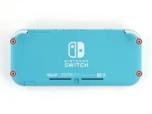
    • Prenez un tournevis Y00 pour dévisser les quatre vis de 6,3 mm de long qui fixent la coque arrière.

    • Tout au long de cette réparation, gardez la trace de chacune des vis et veillez à les revisser toutes là où elles étaient auparavant.

    All my screws got stripped any ideas on how to remove?

    Almost A Mammal -

    A Y0 screwdriver seemed to work better for me.

    Tommy Morrill -

    What type of screw driver do I use to un screw the screws and which way

    Luca Capito -

    Y 0.6 was all I had but it seemed to fit perfectly

    Trevor -

  2. LoododBfWX565CM3
    LoododBfWX565CM3
    axePI5XqFET5KVdd
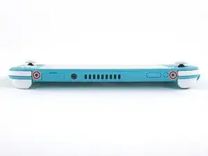
    • À l'aide d'un tournevis cruciforme, dévissez les vis suivantes qui fixent la coque arrière :

    • Deux vis de 3,6 mm de long en haut de l'appareil

    • Deux vis de 3,6 mm de long en bas de l'appareil

    • Pour éviter que ces vis serrées s'abîment, exercez une force ferme vers le bas, travaillez lentement et essayez un autre tournevis si les vis ne sortent pas.

    I accidentally stripped the back screw and now I can't open it. I removed all the other screws. What should I do?

    tiggytiger555 -

  3. OdqFPXbVWUcLdDot
    OdqFPXbVWUcLdDot
    CIVhMktLorQQTIDM
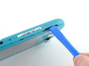
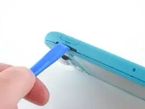
    • Insérez un outil d'ouverture dans la grille du haut-parleur gauche en bas de l'appareil.

    • Faites pivoter l'outil d'ouverture pour défaire les clips qui fixent la coque arrière.

    • Évitez d'insérer l'outil d'ouverture plus profondément que nécessaire. Vous pourriez endommager le module du haut-parleur.

  4. wrE1q1yNyF2ogBV4
    wrE1q1yNyF2ogBV4
    Pmw5QYCTejXbIUKw
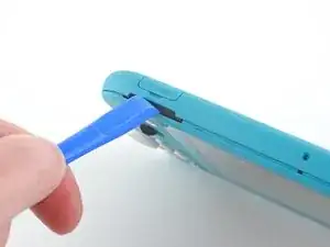
    • Faites glisser l'outil d'ouverture le long du coin inférieur gauche pour ouvrir les clips du côté gauche de l'appareil.

  5. RlPaVdXmyVJlvRdR
    RlPaVdXmyVJlvRdR
    xpNFcLWpxIZGYAZo
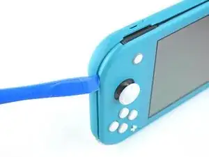
    • Insérez un outil d'ouverture dans la grille du haut-parleur droit en bas de l'appareil.

    • Faites pivoter votre outil pour détacher les clips.

    • Éviter d'enfoncer l'outil plus profondément que nécessaire. Vous risqueriez d'endommager le module du haut-parleur.

  6. nKd22DZNmOtktjJ6
    nKd22DZNmOtktjJ6
    ZFI5WyJ26AuYMJ34
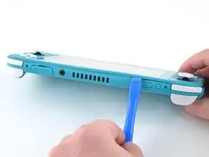
    • Faites glisser l'outil d'ouverture le long du coin inférieur droit pour défaire les clips du côté droit de la console.

  7. UB4MQPADBNC3AKGp
    UB4MQPADBNC3AKGp
    FDjmileJQ6nKxeRT
    • Progressez avec votre outil le long de la rainure en haut de l'appareil afin d'ouvrir les clips.

  8. 3YVyXRJqMpDtXeYv
    3YVyXRJqMpDtXeYv
    N5JkogvdUb1o4kID
    ZH5AGwN3bXMGGKnl
    • Soulevez le bord inférieur de la coque arrière, à la manière d'un livre.

    • Enlevez la coque arrière.

  9. vsR2tYTiCfHGSlh1
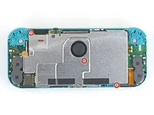
    • Avec un tournevis JIS 000 ou un tournevis cruciforme iFixit PH 000, dévissez les quatre vis suivantes :

    • Trois vis de 3,1 mm

    • Une vis de 4,5 mm

    There are four screws instead of three mentioned

    Khurram Chaudry -

    it doesnt mention 3 anywhere, and it labels all four

    Ezi -

    With how easy it seems to be to do serious damage with the next few steps, I figured I'd say that realistically you can skip steps 9-13 when doing this repair. While they provide a bit of extra security by disconnecting the battery, the left stick is completely accessible and replaceable without touching the heat shield or anything underneath (And steps 17 and 18 disconnect power from the daughter board regardless).

    Nate -

    i stripped a &&^&^$^ screw

    SpongebobFan254 -

    Well I actually removed the screw right next to the 4.5 screw. I did not realize it till my son showed me why the plate wouldn't release. Ha ha, it's funny now but yeah not a big deal. I could have bent it badly assuming I took all screws out though. For anyone reading this before going in. 👍

    Toastninja -

  10. FIwGjkfOhVmFCyvp
    FIwGjkfOhVmFCyvp
    LUwt2Ov3TDBmbBMy
    CxSr6WAFIqTkPknC
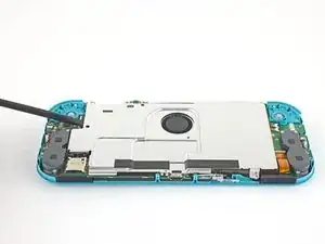
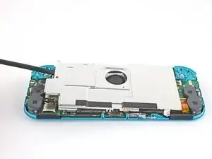
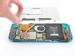
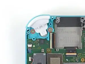
    • Avec une spatule ou vos doigts, soulevez la plaque de protection vers le haut et sortez-la de la console.

    • Peut-être qu'elle résistera. C'est normal, car la plaque de protection adhère légèrement au dissipateur thermique avec de la pâte thermique.

    • Retirez la plaque.

    • Nettoyez les résidus de pâte thermique de la plaque de protection et du dissipateur thermique avec de l'alcool isopropylique et un chiffon en microfibre. Posez une nouvelle couche de pâte thermique sur le dissipateur avant le remontage.

    You may need to replace the thermal paste on the heat sink.

    ahoz28 -

  11. NfJ4EyXkJrCSjyMP
    NfJ4EyXkJrCSjyMP
    SWRCDlfTfCNLuWJO
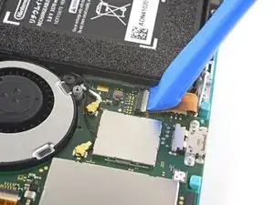
    • Prenez un outil d'ouverture ou votre ongle pour retourner le petit clapet qui verrouille le connecteur ZIF de la nappe d'interconnexion de la carte mère.

    The clip broke off when trying to remove this cable. Audio only works through headphones and the display now won’t turn on after the clip broke. Does anyone know where I could get a clip or how I could fix it without it?

    Alexz Zepeda -

    Mi è successa la stessa cosa è non so come ripararla! Chissà se c’è un modo!

    Paolo De Falco -

  12. EOLi3GutoqJNvstI
    EOLi3GutoqJNvstI
    hO2FmA16pHiJq2to
    • N'utilisez pas de pincette métallique ! Certains réparateurs disent que les pincettes métalliques peuvent court-circuiter le connecteur ou la nappe. Il serait plus prudent d'utiliser des pincettes à pointes en nylon ou en céramique.

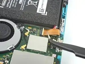
    • Avec une pincette, faites glisser la nappe d'interconnexion hors de sa prise sur la carte mère.

    I turned the unit off beforehand, I used tweezers just like the instructions said (ifixit branded) , my device sparked and now it won’t turn back on

    User Service -

    The flap came off is it important or is there a way t fix it?

    Jose Cruz R Rangel Cordero -

    We're you able to get it working without the white flap? My screen is not working after putting it back together and i noticed this white flap was falling off

    Jimmy “Ghost” Trost -

    Did you get it working without the white flap? Everything on the switch works fine except for audio going through headphones and the display not turning on.

    Alexz Zepeda -

    do not use metal sharp pointed tweezers! you will rip your ribbon cable. Use the inside of a Bic type pen or something else dull and plastic to pull the cable away by putting the pen part where the first bend is.

    Christopher Bales (C.J.) -

    Anyone figure out how to fix this? my device shorted in this step.

    Acord -

  13. yfTkAmQeCWGhAEl2
    yfTkAmQeCWGhAEl2
    SFobIivmPhWAmdMb
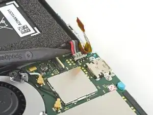
    • Prenez la pointe de la spatule pour soulever le connecteur de la batterie tout droit hors de sa prise sur la carte mère.

    Caution the connector may not be properly soldered onto the motherboard. For me it snapped off the pins and now have to find a place to get that fixed if even possible. may have bricked it.

    Craig Osman -

    Yup, broke the connector right off the motherboard. Thanks, ifixit -_-

    Justin Kerr -

    I backed out when I reached this point. I couldn't risk damaging it. Do u just need to pull it up? Did you mean that it might have been soldered shut below?

    Jannalyzer -

    You should just need to pull straight up, but make sure you’re pulling on the wires or the gray plug—do not pull on the black socket or it can snap off of the motherboard.

    Adam O'Camb -

    I pulled straight up from the south side on under 2 or three wires and held down the device as I pulled and the gray connector disconnected from the black connector on the Switch. Just be careful at this part.

    Jon -

    With how easy it seems to be to do serious damage at this point, I figured I'd say that realistically you can skip steps 9-13 when doing this repair. While they provide a bit of extra security by disconnecting the battery, the left stick is completely accessible and replaceable without touching the heat shield or anything underneath (And steps 17 and 18 disconnect power from the daughter board regardless).

    Nate -

    just broke my connector... ifixit PLEASE put a warning on how fragile the solder on this connector is.

    Nate Mascis -

    Note for this step, you do not need to apply a lot of force. I used two tools here: small screwdriver to hold down the black base, and one side of fine-tipped tweezers to get under all 3 wires. Gently, push down on the tweezers to push the wires upwards, which should force the gray connector up and off the base. It did not take a lot of force. Take your time and it will be fine. Again, like others have said, do NOT pull or pry up the black base.

    Christopher Gillett -

  14. iuutsxvMo3TxGutF
    • Servez-vous de l'extrémité plate d'une spatule ou de vos doigts pour décoller la mousse qui adhère légèrement au ventilateur.

    • Il suffit de décoller la mousse de ce qu'il faut pour dégager le ventilateur.

    When reassembling, the foam may fold down between the fan and heatsink, blocking airflow. Gently lift the foam back up on top of the fan. The adhesive film should hold the foam together.

    Kean Stump -

    Is removing the heat sink absolutely necessary?

    Clark Aulden -

    It’s not necessary, but it makes it much easier to remove and replace the game card reader, since the heat sink partially covers the connector.

    Craig Lloyd -

    Not really…….. I never remove it. It slides out quite easily once disconnected.

    Alan Sears -

    What do you do if these screws are stripped? They strip easily

    Whatever -

  15. QWMQ2YrSy4JCPv4E
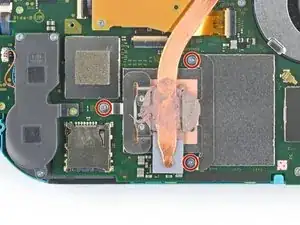
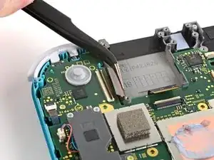
    • Avec un tournevis JIS 000 ou un tournevis iFixit PH 000, dévissez les trois vis de 3 mm qui fixent le dissipateur thermique à la carte mère.

    Non le tre ventole ma le tre viti

    Cristiano Minchillo -

    Grazie per avercelo segnalato! Ho apportato la modifica. iFixit è una wiki, quindi ogni utente può modificare le pagine: se trovi altri errori in futuro, sentiti libero di fare la modifica tu stesso!

    Sara Balestra -

  16. 4x22rRB1EQtWewRL
    4x22rRB1EQtWewRL
    jBHwjFqQxbHLBpjV
    bXVdT31XEDGyDS5L
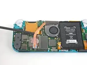
    • Avec une spatule ou vos doigts, soulevez le dissipateur thermique pour le détacher de la carte mère et le retirer.

    • Peut-être que le dissipateur résistera. C'est normal car il adhère légèrement au processeur avec de la pâte thermique.

    • Nettoyez les résidus de pâte thermique du dissipateur thermique et du processeur avec de l'alcool isopropylique et un chiffon en microfibre. Posez une nouvelle couche de pâte thermique sur le processeur avant le remontage.

    16.5 remove cartridge / headphones jack……….

    Calvin Martin -

    I've read that there are different ways to apply thermal paste, which should I use?

    Kai B -

    My kit did not come with thermal paste..

    Bryan Donovan -

  17. KrXqYGqKyhavqmAm
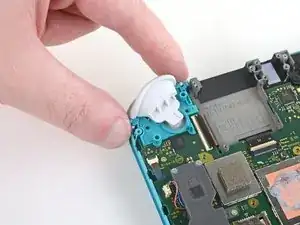
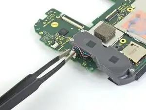
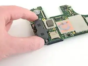
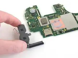
    • Avec un tournevis JIS 000 ou un tournevis cruciforme iFixit PH 000, dévissez les deux vis de 4,5 mm qui fixent le module de la gâchette droite à la carte mère.

    I think a whole step to remove the game card reader and speaker jack was skipped here…

    ConfusedAzn Random -

    yes, just found that sadly these comments do not show unless we click on the , which is unhelpful

    Micheal speed -

    also, you need to remove the left trigger button

    Micheal speed -

  18. 5lu12BIJX1YVqAn2
    5lu12BIJX1YVqAn2
    JqP15TQm6YEPY2LD
    • Enlevez le module de la gâchette droite.

  19. chqnDc31GYFROsZw
    chqnDc31GYFROsZw
    xiBauSfiZNTfHMTR
    • Avec une pincette ou vos doigts, retirez le dispositif en caoutchouc du module de la gâchette droite s'il ne s'est pas détaché en même temps que le module.

  20. xcOWWVkaeBgFKHal
    xcOWWVkaeBgFKHal
    24CeDyxGrpjSn1Za
    1lPMeSKxkRAeXsx5
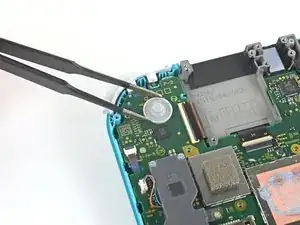
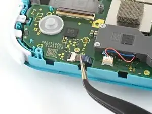
    • Faites levier avec la pointe d'une spatule sur le câble d'antenne noir pour le sortir de sa prise sur la carte mère.

    • Répétez la procédure pour le câble d'antenne blanc.

  21. GoxOWhyctZE5h3Vb
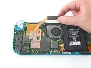
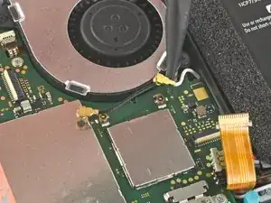
    • Servez-vous d'un outil d'ouverture ou de votre ongle pour retourner le petit clapet de retenue du connecteur ZIF de la nappe du ventilateur.

  22. lyZ4AOAU4AZl5tqe
    lyZ4AOAU4AZl5tqe
    wRLrI3jwCANoNyju
    • Faites glisser la nappe du ventilateur hors de son connecteur sur la carte mère à l'aide d'une pincette.

    There’s a step missing after this to remove the screws that hold the orange game cartridge slot. Those 7 screws have to be undone and the ribbon unclipped first before moving on to the next step.

    Heather Thrasher -

    Good Looking out!

    Joshua Hinchey -

  23. FfuwxRxZSkQcVKpi
    FfuwxRxZSkQcVKpi
    4gU2dcBdLmKxWPjo
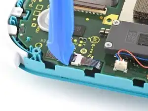
    • Avec un outil d'ouverture ou votre ongle, retournez le petit clapet de retenue du connecteur ZIF de la nappe de l'écran.

    skipped a step or two about removing the golden piece in the photo above, and the other little board

    Eddy Whitaker -

    If I broke the clasp on the ZIF connector can I elec tape it down?

    kevin miller -

    What did you do to fix it if the ZIF connector broke?? Mine did too and I worry that is why the screen won’t turn on now

    Amber Smith -

    Missing the card reader + audio jack board removal. Just remove the 4 screws around the audio jack + 3 screws around the card reader and disconnect the ZIF connector from the motherboard.

    Guillaume Turchini -

  24. wSwylFJAsZW3NgsI
    wSwylFJAsZW3NgsI
    OeV561fN4xH1AcgI
    • Faites glisser la nappe de l'écran hors de sa prise sur la carte mère avec une pincette.

  25. FWkJe1DNdTPNxfFc
    FWkJe1DNdTPNxfFc
    MgI1qpopQRiC1Coj
    • À l'aide d'un outil d'ouverture ou de votre ongle, retournez le petit clapet qui verrouille le connecteur ZIF de la nappe de la vitre tactile.

    Can I electrical tape this down if I broke the clasp?

    kevin miller -

  26. Tp6mukLD3ybSYZfq
    Tp6mukLD3ybSYZfq
    ATK1pvPvge36251G
    • Avec une pincette, glissez la nappe de la vitre tactile hors de son connecteur sur la carte mère.

  27. SxMDga2Qvmmjn5Ar
    SxMDga2Qvmmjn5Ar
    GFUX4uIGXPqnyGqf
    • À l'aide de votre outil d'ouverture ou de votre ongle, retournez le petit clapet de retenue du connecteur ZIF de la nappe du joystick droit.

  28. pEFHSSkWUaqGATlV
    pEFHSSkWUaqGATlV
    eMQ2CE3UiSPwibFF
    • Utilisez la pincette pour faire glisser la nappe du joystick droit hors de sa prise sur la carte mère.

  29. 3GkQQgnWlLlGONVE
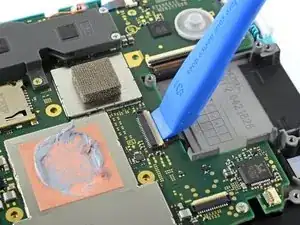
    • Avec un tournevis JIS 000 ou un tournevis iFixit PH 000, dévissez les six vis suivantes qui fixent la carte mère :

    • Trois vis de 3,1 mm

    • Trois vis de 4,5 mm

    how to get the c port off

    Dustin Cronk -

    When re-assembling, be sure the fan cable (step 25) is completely pulled through prior to tightening the screw that’s right next to it.

    John Glaeser -

  30. dKc6KXcUwADISyuy
    dKc6KXcUwADISyuy
    BWklTKR1T4CAQHCW
    cEYHxoErVSYY1wd3
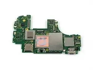
    • Insérez une spatule dans l'espace entre le châssis et la carte mère et soulevez cette dernière vers le haut et hors de son emplacement.

    • Ôtez l'ensemble carte mère.

  31. EE1n6VnUtC6PL4PG
    EE1n6VnUtC6PL4PG
    5MhYN3MRBnt1GVVQ
    • Utilisez une pincette ou vos doigts pour tirer le câble du haut-parleur droit vers le haut et hors de sa prise sur la carte mère.

    What is the little white piece called that the speak cable goes into

    Kieron Torrens -

  32. OkwrrPMqBANZV6hS
    OkwrrPMqBANZV6hS
    xNATiQEFXtAUkrvF
    • Retirez le module de haut-parleur droit de la carte mère.

  33. OxTSdBFgEwqyVK6W
    • Seule la carte mère reste.

    Where do you buy the motherboard if you can buy it

    addser973 -

    Yea where can i get a motherboard from?

    JoyBoy -

Conclusion

Pour remonter votre appareil, suivez ces instructions dans l'ordre inverse.

Déposez vos déchets électroniques dans un point de recyclage certifié.

La réparation ne s’est pas déroulée comme prévu ? Consultez nos conseils basiques de diagnostic ou notre Forum pour obtenir de l’aide.

Craig Lloyd

Membre depuis le 10/02/16

37629 Réputation

7 commentaires

Great guide, helped me fix charge port replacement, did notice between 16-17 the card reader magically disappeared, but help me tear down and repair and rebuild with a little bit of head scratching.

Sean Topp -

La guida è molto chiara.. ma dove si può acquistare una scheda madre di ricambio ?

Walter -

It stops at motherboard removal, is there a section for replacing the USB charging port on the switch lite?

Christian Knight -

Where can i get the motherboard from, i cant replace the charging port, cause it is soldered to the motherboard. So if you could please let me know onto where i can get the mother board from. 😊

JoyBoy -

I have a working motherboard but it is missing one of the resistors (see the green square). How do I find out the value of this resistor? The resistor is situated to the left of the main chip, just below the microSD card slot, if the USB-C port is facing downward.

Christian Odom -

Steps 17-19 from LCD replacement (removing game card reader) are missing from this guide.

Yan -

"To reassemble your device, follow these instructions in reverse order." Got it all back together and never reinstalled the card reader because that part isn't in the instructions.

RJ K -