Introduction

Ce guide vous expliquera comment retirer l'ensemble du panneau avant. Il s'agit d'une étape nécessaire pour remplacer n'importe quelle pièce de la Sonos Play 5.

  1. gPXCbtYRX6jtLsDD
    • Débranchez toute alimentation de l'enceinte et attendez quelques minutes pour que les condensateurs se déchargent complètement.

    • Retournez l'enceinte.

    • Il peut y avoir un pied en caoutchouc recouvrant les vis inférieures (non inclus dans l'image). Retirez-le en tirant vers le haut depuis l'un des coins à l'aide d'une spatule.

    By the time you actually reached the motherboard the capacitors will already be discharged sufficiently to a safe level, so just go ahead there's no need to wait in this step.

    That said, be careful once you have the motherboard out and decide to test it on your table. The two large capacitors are directly behind the full bridge rectifier that's connected to the mains, so without load they carry the peak voltage. In Europe with 230V that means 325V, in 110V countries that means 156V (see https://en.wikipedia.org/wiki/Alternatin... for more information about RMS and peak voltages).

    Erik Mouw -

  2. ssEZ5tToZG3Moihr
    ssEZ5tToZG3Moihr
    jZqJUyInUQGmxQuJ
    • Retirez huit vis cruciformes n°2 de 10mm

    • Retirez le panneau inférieur en tirant vers le haut.

    • Soyez très doux avec les extrémités des trois antennes. Elles sont très fragiles.

    NB: in the photograph, two antennas of the three soldered on the antenna PCBs are broken: You can see one standing upside down towards the center-right of the photograph

    Toni -

    On my model, only 6 of the 8 screws hold the bottom panel. Looking at the picture above, where the screws are circles, the bottom row of 5 screws, the second and fourth screw are threaded for nuts, as opposed to the other six, which are threaded for plastics. These two screws can be removed once the bottom panel has been removed.

    Toni -

    Like the previous poster said: in this step it is sufficient to remove the second and fourth screw cause these hold the front panel. Removing the front panel takes a bit of force and it is better to have the fragile WiFi antennas protected by the bottom panel.

    The remaining six screws can be removed just before step 13 (which also misses a step, see my comments over there).

    Erik Mouw -

  3. STWtAoFNiinNbhup
    STWtAoFNiinNbhup
    tX1HXstZLJtGl1On
    rbFRqxBkFDbVaZnN
    • Retournez l'appareil de sorte que la grille soit orientée vers le haut.

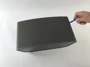
    • Localisez la ligne sur le côté droit de l'enceinte où la grille et le plastique se rencontrent, et placez votre spatule en plastique dans l'interstice.

    • Passez la spatule le long de l'interstice, en détachant la grille du plastique. Répétez aussi ce processus sur le côté gauche.

    • Tirez doucement sur la grille, en la retirant du panneau avant.

    might be worth mentioning there are two strips of industrial velcro running along near the top and bottom that simply have to be pulled apart

    Adam Tibbalds -

    Run the plastic opening tool under the grille to remove to pull the velcro apart. In that way you avoid bending the grille. Be careful with the speaker cones, though.

    Erik Mouw -

  4. KUcjokm6wtXCLifZ
    • Retirez les six vis cruciformes n°2 de 8mm.

    • Retirez les deux vis cruciformes n°2 de 10mm.

    In my unit the top two screws marked in red had a rubber plug in the hole as well. I had to remove them by sticking a knife in and carefully pulling them out.

    Adam Tibbalds -

    I had the same issue but no problem getting them out.

    clarkal2000 -

    I pulled them out using the corkscrew method: I drove a screw about 10mm deep into the rubber plug, then pulled up the screw. This method created way less damage than other methods i have tried.

    Toni -

  5. cLVG4SfPrbcrXUjo
    cLVG4SfPrbcrXUjo
    JnIQdCgHvKhtcOVd
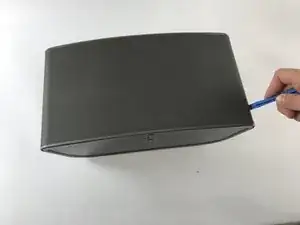
    • Repérez la ligne sur le côté droit où le panneau avant et le panneau arrière se rencontrent. Placez une spatule en plastique dans l'interstice et faites-le courir le long de l'espace. Répétez cette opération sur le côté gauche.

    • Utilisez la spatule pour soulever la plaque avant. Si une spatule en plastique ne fournit pas un effet de levier suffisant, utilisez une spatule en métal.

    • Tirez doucement sur la plaque frontale pour vous assurer qu'elle a été détachée du boîtier.

    • Lorsque vous tirez sur la plaque frontale, soyez prudent car elle est toujours connectée par des fils à l'arrière de la plaque.

  6. GMOtKHefETYH4XLC
    GMOtKHefETYH4XLC
    pUJgkNe2yMRKO6TY
    fZbdDKnQrUrLDVmH
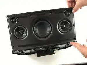
    • Soulevez le panneau avant en formant un angle de 90 degrés avec le panneau arrière. Localisez le connecteur à dix contacts comme indiqué. C'est le câble qui relie le panneau avant au panneau arrière.

    • Appuyez sur la petite languette située sur le connecteur. Avec la languette fermement enfoncée, retirez le connecteur de son embase.

    • L'assemblage de la façade est maintenant entièrement détaché du reste de l'enceinte.

    my unit didn’t have the tab in the middle of the connector. It simply had to be prised apart (I used a plastic spudger to separate the two parts of the connector) and then reconnected carefully (I used the plastic spudger again between the pcb and the case to support the pcb as it was flexing)

    Adam Tibbalds -

    My unit has a white gasket between the front and back panel. It was stuck to the front panel when I opened the unit. When rebuilding the unit it was easier to remove the gasket and put it in the small ridge of the back panel.

    Erik Mouw -

Conclusion

Pour remonter votre appareil, suivez ces instructions dans l'ordre inverse.

Steven Gioiosa

Membre depuis le 20/02/17

274 Réputation

0 commentaires