Introduction
Chaque réparateur devrait savoir utiliser un multimètre, qui permet de tester les composants et circuits électroniques. Suivez ce tutoriel pour maîtriser les trois fonctions de base d'un multimètre.
Partie 1 : Tester la continuité
Partie 3 : Mesurer la résistance
Afin d'apprendre à utiliser votre multimètre pour faire des mesures avancées comme le courant ou la capacité, suivez ce tutoriel.
Outils
-
-
Un test de continuité nous indique si deux choses sont connectées électriquement : si c'est continu, le courant électrique peut circuler librement d'un bout à un autre.
-
S'il n'y a pas de continuité, cela signifie qu'il y a une coupure quelque part dans le circuit. Cela peut signifier un tas de choses, d'un fusible grillé à un joint mal soudé en passant par un circuit mal connecté.
-
-
-
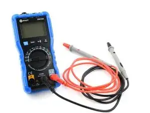
Branchez la fiche noire dans le port COM de votre multimètre.
-
Branchez la fiche rouge dans le port où il est indiqué "V" (dans notre cas, le port de droite).
-
-
-
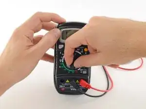
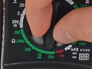
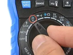
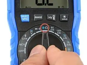
Allumez votre multimètre et réglez le cadran en mode continuité (indiqué par une icône qui ressemble à une onde sonore).
-
-
-
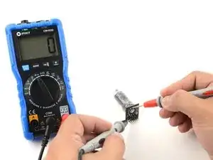
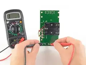
Pour terminer votre test de continuité, placez une pointe à chaque extrémité du circuit ou du composant à tester.
-
Pour vérifier ce phénomène, inversez les pointes et re-vérifiez la continuité. Si le multimètre affiche une continuité, alors il y a potentiellement une diode dans le circuit.
-
-
-
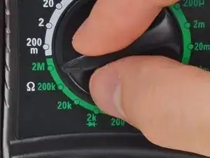
Tournez le cadran jusqu'au mode résistance.
-
Si le choix des calibres est manuel sur votre multimètre, choisissez le calibre le plus bas.
-
-
-
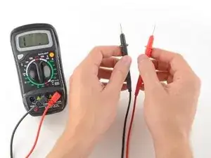
Dans ce mode, le multimètre envoye un peu de courant à travers une pointe, et mesure ce qui est reçu par l'autre pointe.
-
Si les pointes sont connectées (soit par circuit continu, soit en se touchant directement l'une l'autre) le courant test circule à travers. L'écran affiche une valeur de zéro (ou proche de zéro, dans notre cas 0,8). Une très faible résistance est une autre manière de dire que nous avons la continuité.
-
Si le courant n'est pas détecté, cela signifie qu'il n'y a pas de continuité. L'écran affichera 1 ou OL ("open loop", soit circuit ouvert).
-
-
-
Pour terminer votre test de continuité, placez une pointe au bout de chaque circuit ou composant que vous voulez tester.
-
Comme précédemment, si votre circuit est continu, l'écran affiche une valeur zéro (ou proche de zéro).
-
Si l'écran affiche 1 ou OL (circuit ouvert), il n'y a pas de continuité, ce qui signifie qu'il n'y a pas de chemin pour le courant électrique pour circuler d'une pointe à une autre.
-
-
-
Insérez la fiche noire dans le port COM de votre multimètre.
-
Insérez la fiche rouge dans le port indiqué par le symbole V (dans notre cas, le port de droite).
-
-
-
Allumez votre multimètre et réglez-le en mode tension DC (indiqué par un V avec une ligne droite ou le symbole ⎓). ("DC" = "direct current" = "courant continu (CC)", NdT)
-
Chaque indication sur le cadran indique la tension maximale que le calibre peut mesurer. Comme par exemple, si vous pensez mesurer plus de 2 volts mais moins de 20, alors utilisez le calibre 20 volts.
-
Si vous n'êtes pas sûr.e, commencez avec le calibre le plus élevé.
-
-
-
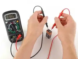
Placez la pointe rouge sur la borne positive, et la pointe noire sur la borne négative. Le multimètre affiche alors la tension mesurée.
-
Sautez l'étape suivante, qui décrit comment choisir soi-même le bon calibre de mesure.
-
-
-
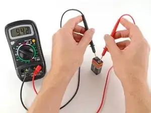
Placez la pointe rouge sur la borne positive, et la pointe noire sur la borne négative.
-
Si le calibre sélectionné est trop haut, la mesure sera moins précise. Ici, le multimètre affiche 9 volts. C'est bien, mais en sélectionnant un calibre plus petit, on aura une mesure plus précise.
-
Si le calibre sélectionné est trop bas, le multimètre affiche simplement 1 ou OL, indiquant qu'il surcharge ou qu'il est hors limite de détection ("OL" = "over limit" = "hors limite", NdT). Cela n'abîme pas le multimètre, mais il faut régler le calibre plus haut.
-
-
-
Pour commencer, assurez vous qu'aucun courant ne passe à travers le circuit ou le composant que vous voulez tester. Éteignez-le, débranchez la prise électrique du mur et retirez toutes les batteries.
-
Insérez la fiche noire dans le port COM de votre multimètre.
-
Insérez la fiche rouge dans le port indiqué par le symbole Ω, dans notre cas le port de droite.
-
-
-
Placez une pointe à chaque extrémité du circuit ou du composant, dont vous souhaitez mesurer la résistance.
-
Si votre multimètre est manuel :
-
Si votre multimètre affiche une valeur proche de 0, le calibre est trop gros pour une bonne mesure. Dans ce cas, diminuez le calibre en réglant le cadran sur une plage inférieure.
-
Si votre calibre est trop petit, le multimètre indique simplement 1 ou OL, signifiant qu'il est surchargé ou hors limite. Cela n'endommagera pas le multimètre, mais il faut augmenter le calibre.
-